Up, and not eating the Starlink
The DX Commander is built, guyed, fed and on the air. It took longer than it should have, the base was designed and printed the night before, and the one thing that was genuinely worried about — 100 watts from the Flex walking all over the site internet — did not happen at all.
A build day with a result. If you want the numbers, the analyser readings are all here, including the band that refuses to play.
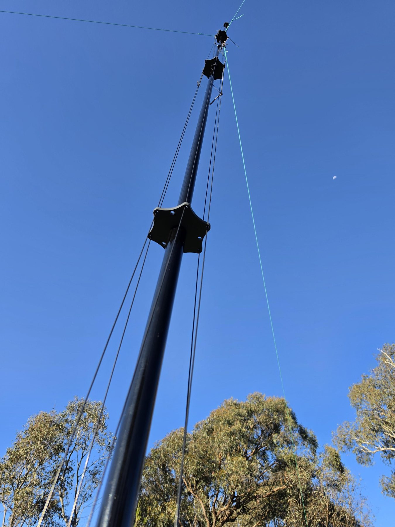
Success. The vertical at Spring Range is no longer a pole standing in a paddock looking impressive and doing nothing — which is exactly what last visit honestly admitted it was. It is now a properly built, properly guyed, properly fed multiband antenna, and it works.
Two days, not one
Saturday was the cutting. VK1MDA came and helped measure and cut the elements and the ground radials, which is the part of a multiband vertical that is tedious rather than difficult — a lot of wire, a lot of measuring, and every mistake costs you the length permanently. Having a second pair of hands for it turned a long job into a manageable one. Thanks VK1MDA.
Sunday was the assembly, on site, from parts. It took longer than it was supposed to. That is worth writing down rather than glossing over, because it is the norm and not the exception: the job that looks like a morning turns into most of a day once you are actually standing in a paddock working out which wire goes to which tab, with no bench, no spare hardware, and the wind picking up.
The red base
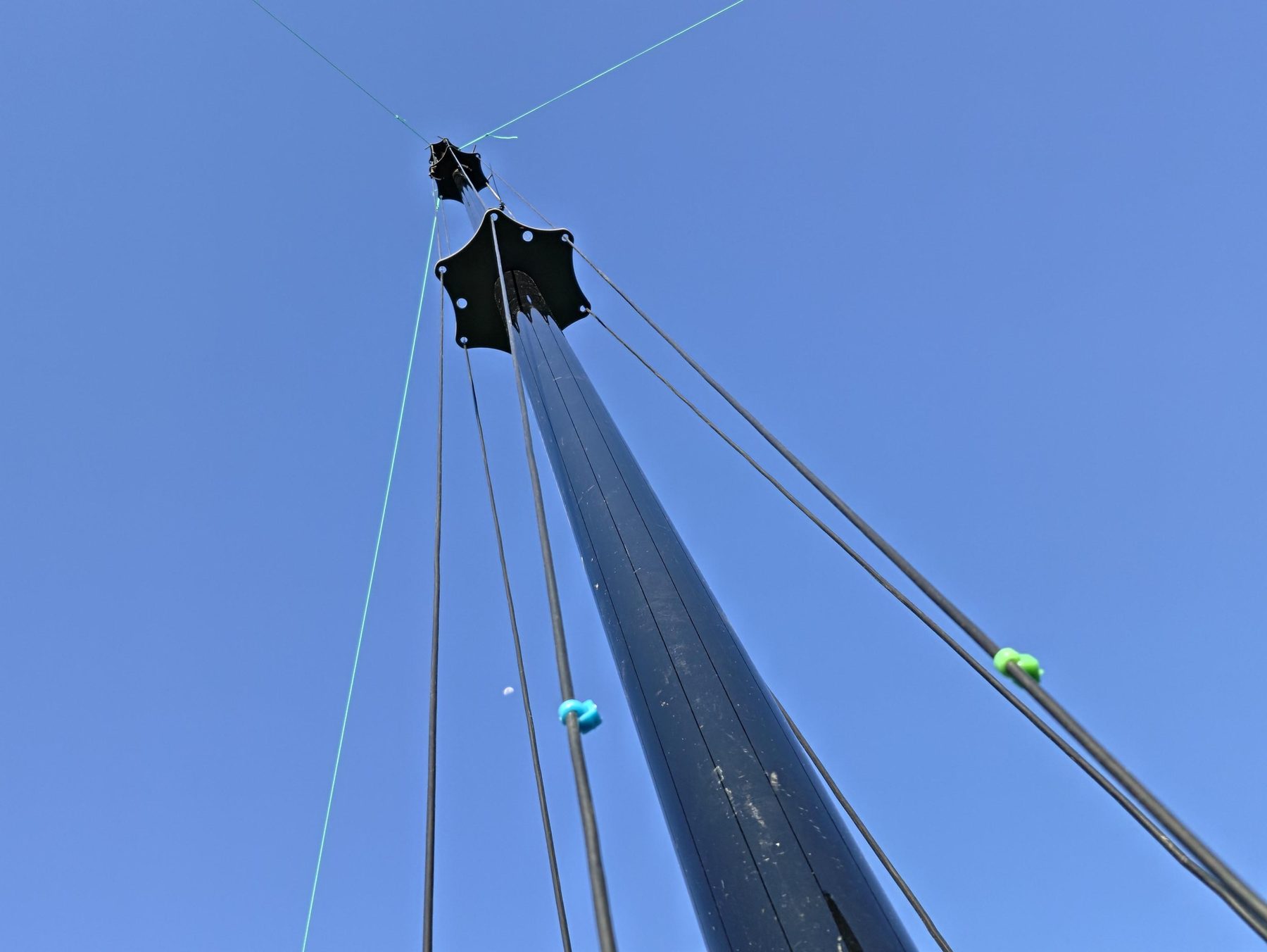
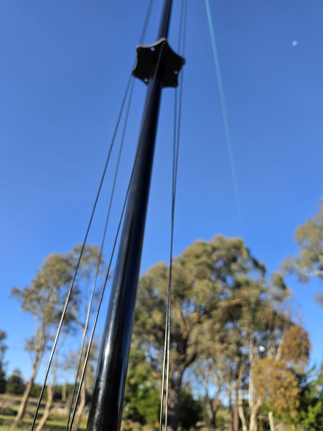
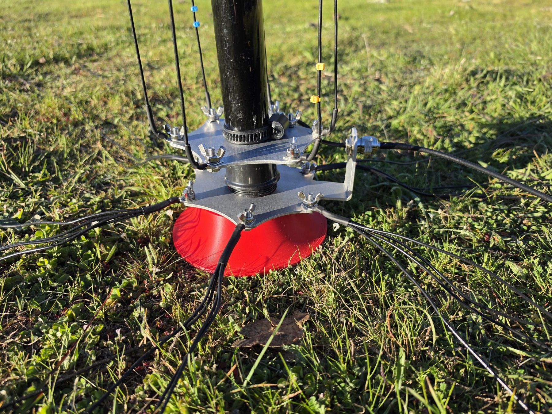
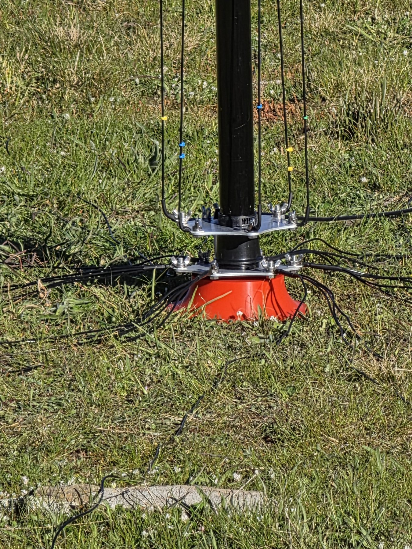
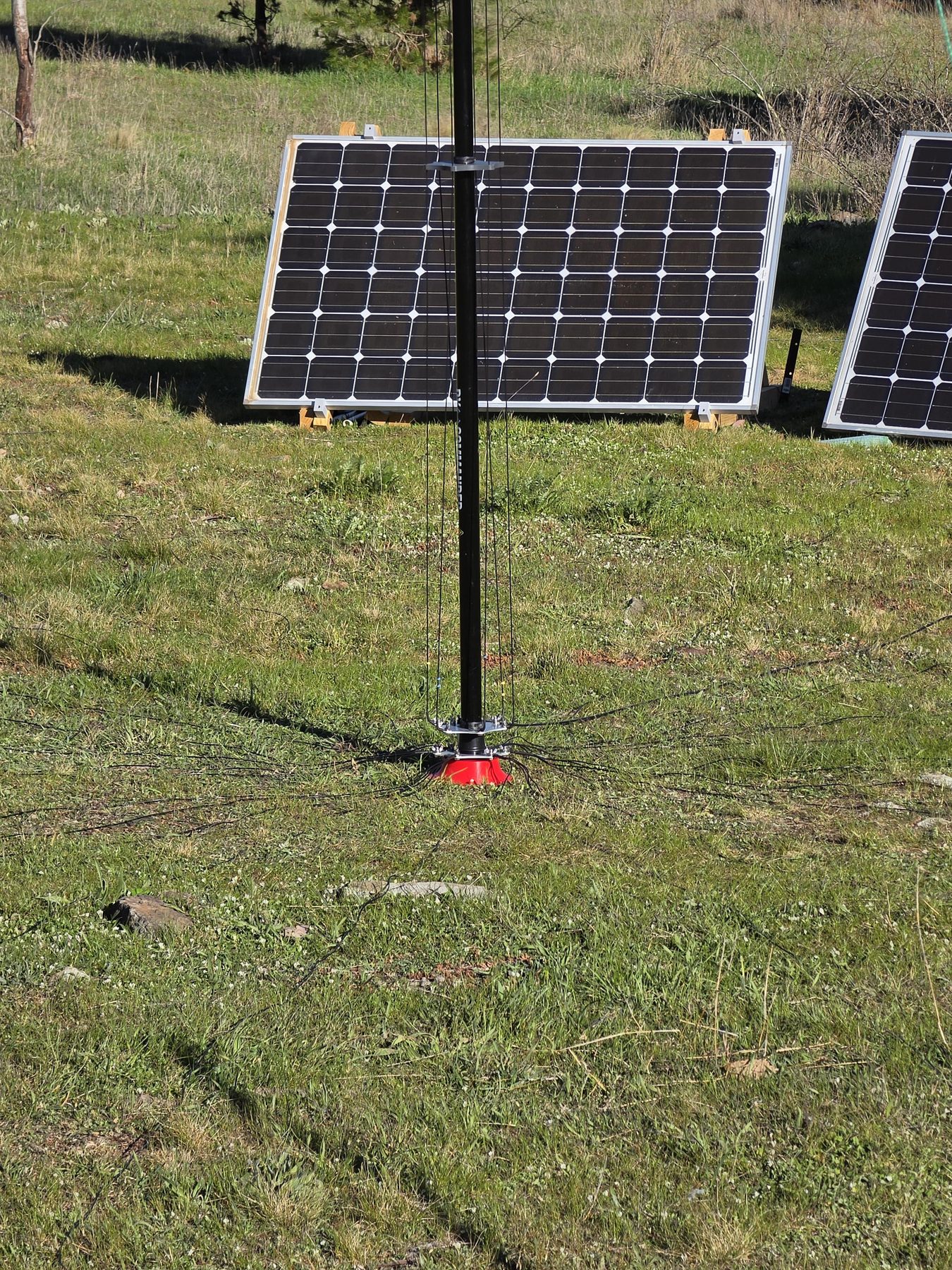
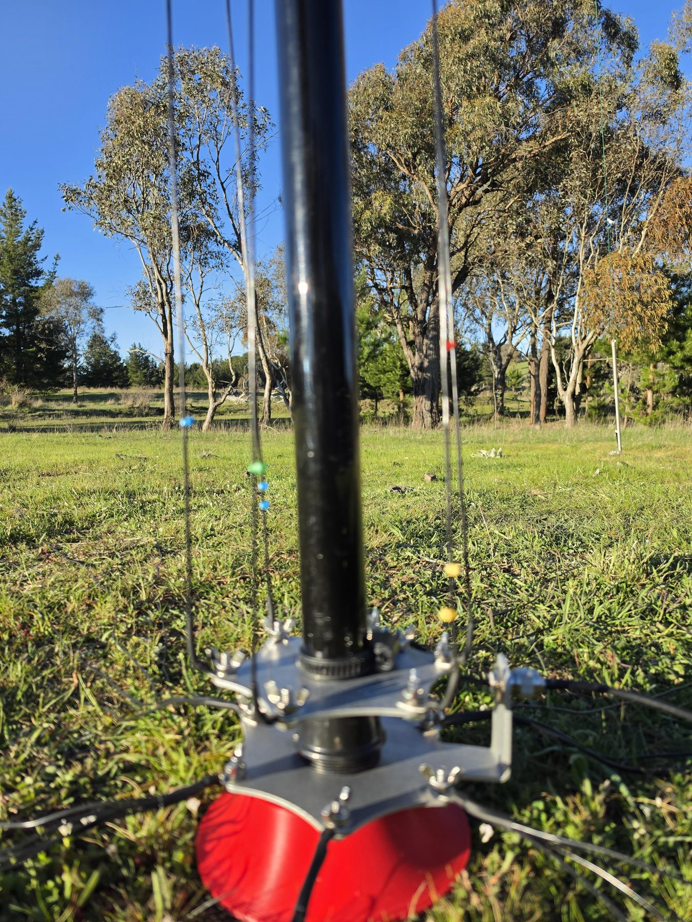
The base was designed and 3D printed the night before. It slides down over a small garden stake driven into the ground, and its whole job is to hold the bottom of the mast exactly where it should be while the radials and elements pull on it from every direction at once.
It is a small part and it is the difference between an antenna that stays put and one that wanders off centre the first time the wind gets into it. A vertical with a fan of elements and a spread of radials is, structurally, a thing that wants to lean — everything attached to it is pulling down and outward. Giving the base one fixed, repeatable position over a stake means the antenna goes back up in the same place and the same attitude every time it comes down.
The thing that was actually worrying
The real question of the day had nothing to do with whether the antenna would radiate. It was whether transmitting at all would take the site off the internet.
A few weeks back a temporary antenna went up here — a random end fed half wave with no ground and no counterpoise, which is to say a half-finished antenna. It loaded, and it radiated, but a good deal of the radio frequency current went back down the outside of the coax rather than into the sky, and it caused havoc with the Starlink every time the key went down. That is common mode current doing exactly what it does: an antenna with nowhere proper to return its current will happily use the feedline, the ground and anything else conductive in the vicinity, and a satellite terminal on the same patch of ground is squarely in the vicinity.
So the question for today was simple and unpleasant: does 100 watts out of the Flex take the station's own connection down? If it did, a remote station has a genuine problem, because everything here — the SDRs, the telemetry, the radio itself — is reached over that link.
No such issues. Nothing dropped, nothing stuttered, no reboots. A properly grounded vertical with a real radial field gives the current somewhere to go, and it turns out that is not merely theory. That single result is worth more than the antenna itself, because it is what makes transmitting from here compatible with operating from here.
Where it is resonant
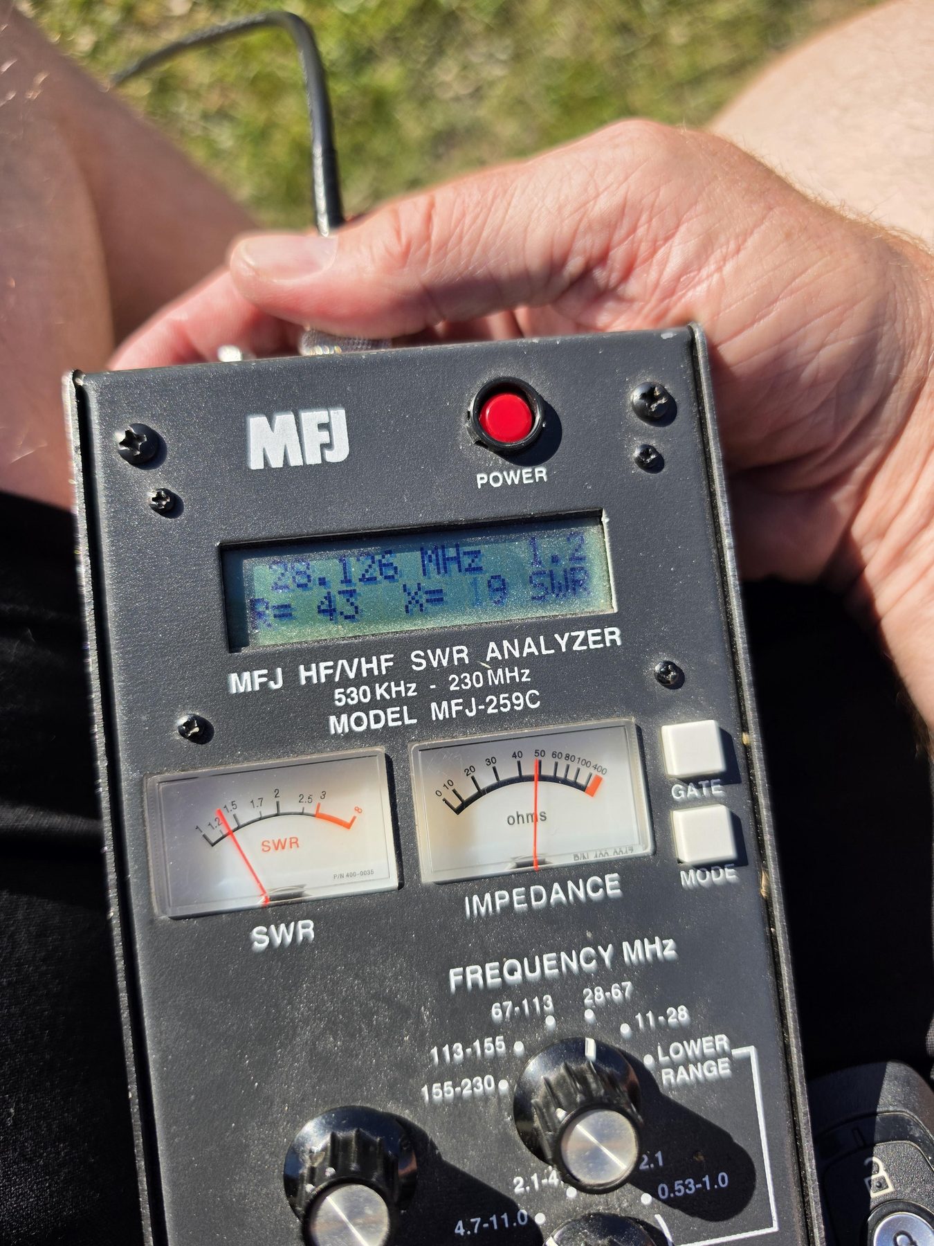
The analyser came out and the numbers are good — and good in the right direction.
| Frequency | SWR | R | X | Note |
|---|---|---|---|---|
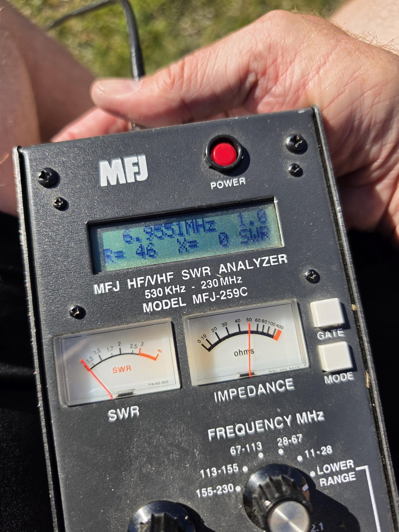
| 6.9551 MHz | 1.0 | 46 | 0 | ~45 kHz below 40m |
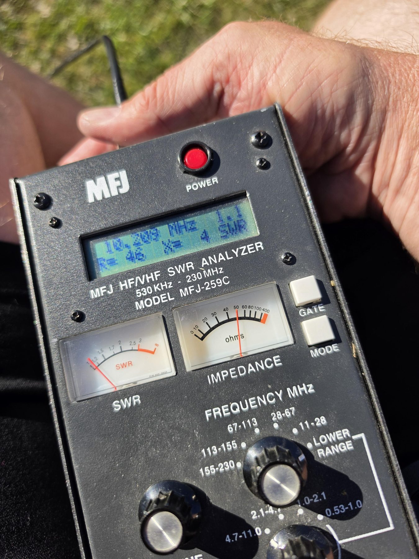
| 10.209 MHz | 1.1 | 46 | 4 | just above 30m |
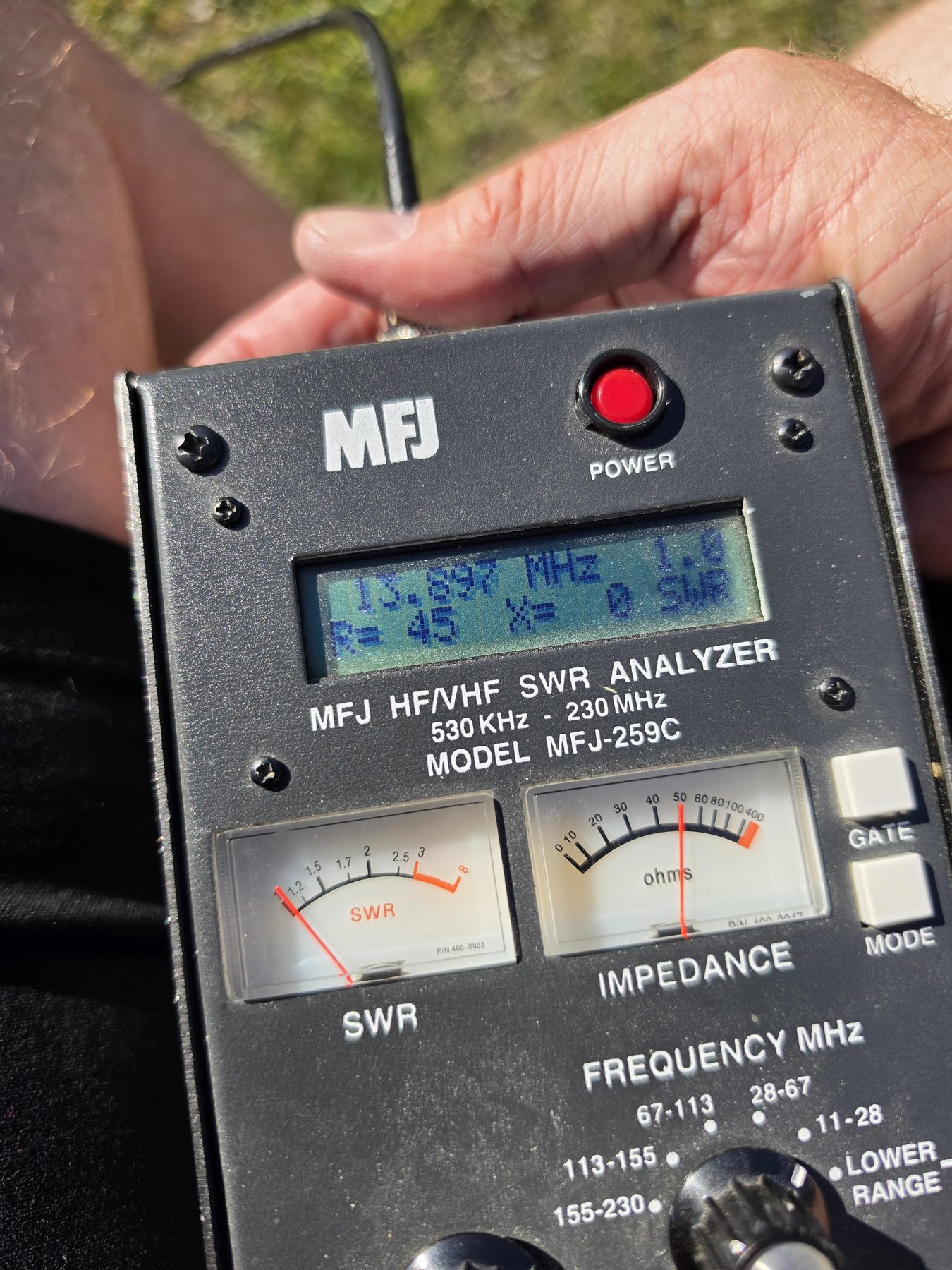
| 13.897 MHz | 1.0 | 45 | 0 | ~100 kHz below 20m |
| 28.126 MHz | 1.2 | 43 | 19 | in the 10m band |
Resistances in the mid forties with reactance at or near zero is about as clean as a ground mounted vertical gets. More to the point, the dips are mostly sitting below where they want to be, and that is the right mistake to make. An element that is too long is a pair of side cutters and five minutes; an element that is too short means splicing wire back on, or cutting a new one. Low is a trim. High is a rebuild.
Except twenty metres
Twenty will not tune. Not marginally, not with the tuner working hard — not at all. Something has clearly been done wrong on that element, and no amount of optimism about the other bands changes it.
There is a clue sitting in the table above, though. The 13.897 MHz dip is almost exactly twice 6.9551 MHz. A quarter wave element on forty metres is a half wave at twice the frequency, and a half wave fed against ground presents a high impedance, not a low one — so a clean-looking dip just under fourteen megahertz may not be the twenty metre element answering at all. It may be the forty metre element's second harmonic, with the actual twenty metre element not connected, not making contact at the plate, or not doing anything useful at all.
That is a theory rather than a diagnosis. But it is a testable one, and it is the first thing to check next visit: disconnect forty at the plate and sweep again. If the dip at 13.9 disappears, the answer is at the terminal, not in the wire.
On the air
A quick CW test to finish. Listening back through the Iron Range SDR — well to the south east, and a fair test of whether anything is actually leaving the paddock — the signal was a solid S9.
That is the whole point of the exercise. The station can now transmit, it gets out, and it does not knock itself off the internet while doing it. Everything after this is refinement.
What changed
- Antenna DX Commander properly built, guyed and fed — no longer a temporary mount
- Antenna Elements and ground radials cut and fitted, with help from VK1MDA
- Base Custom base designed and 3D printed, locating over a ground stake
- RFI 100 W from the Flex caused no Starlink disruption — the common mode problem seen with the temporary end fed is gone
- Tuning Resonance confirmed on 40m, 30m and 10m; dips sit low, which is the trimmable direction
- Tuning 20m will not tune — unresolved
- Operating CW test into the Iron Range SDR at S9
Next visit
- Tuning Find out what is wrong with 20m — start by disconnecting 40m at the plate and re-sweeping to see whether the 13.9 MHz dip is really the 20m element
- Tuning Trim 40m up into the band — roughly two per cent off the element
- Tuning Check what the 10.209 MHz dip actually belongs to; it sits above 30m, not below it, which is the opposite of everything else
- Antenna Leave 10m alone — it is already in the band at 1.2